Intro
We just had reading week, followed by Design Week. Over reading week I figured it was a good idea to do some work on the Mazda before winter comes and hits. I swapped over to my winter tires and gave her an oil change, but this blog is about the cool tech I've added!
Heated Seats
The first thing I wanted was heated seats. I had seen videos of people installing kits, so I had one sitting around for a few months before I decided that now was the ideal time to install them.
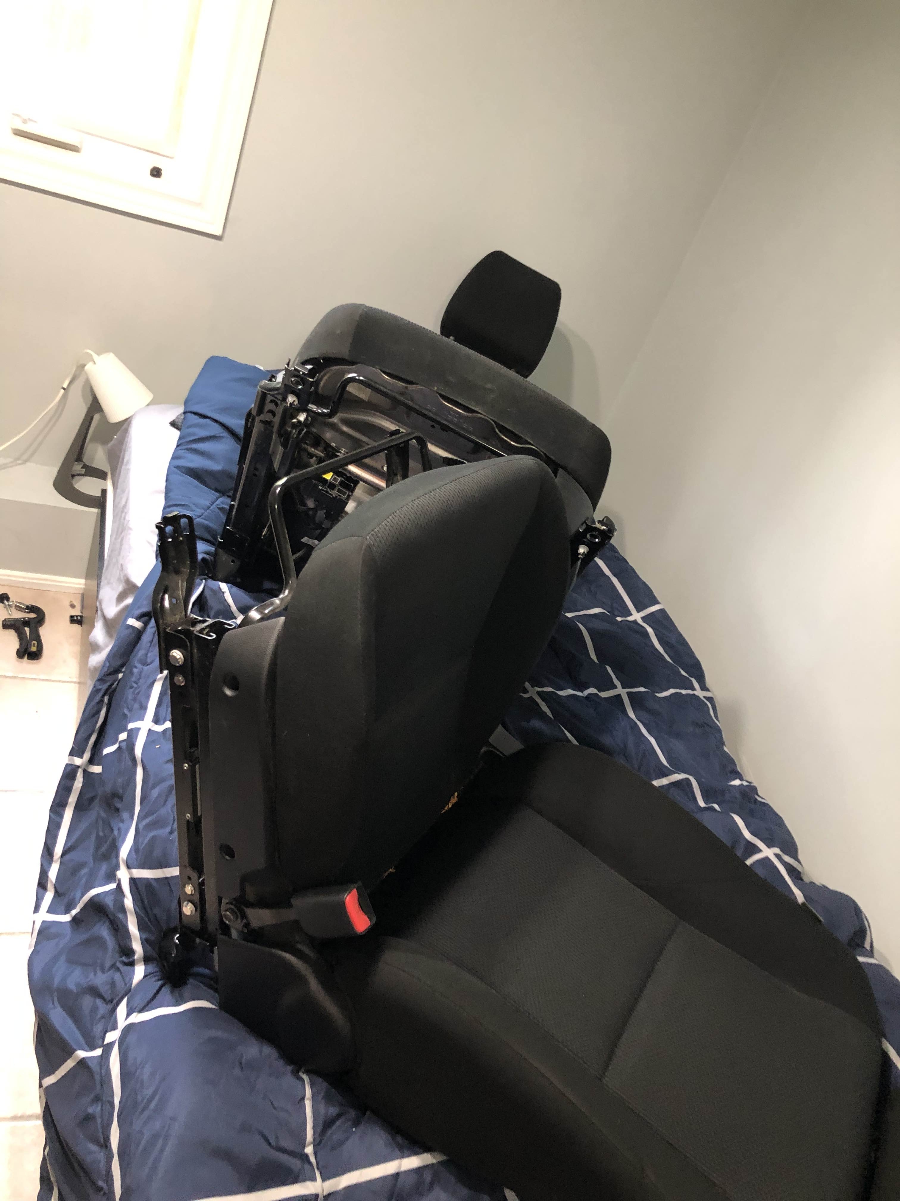
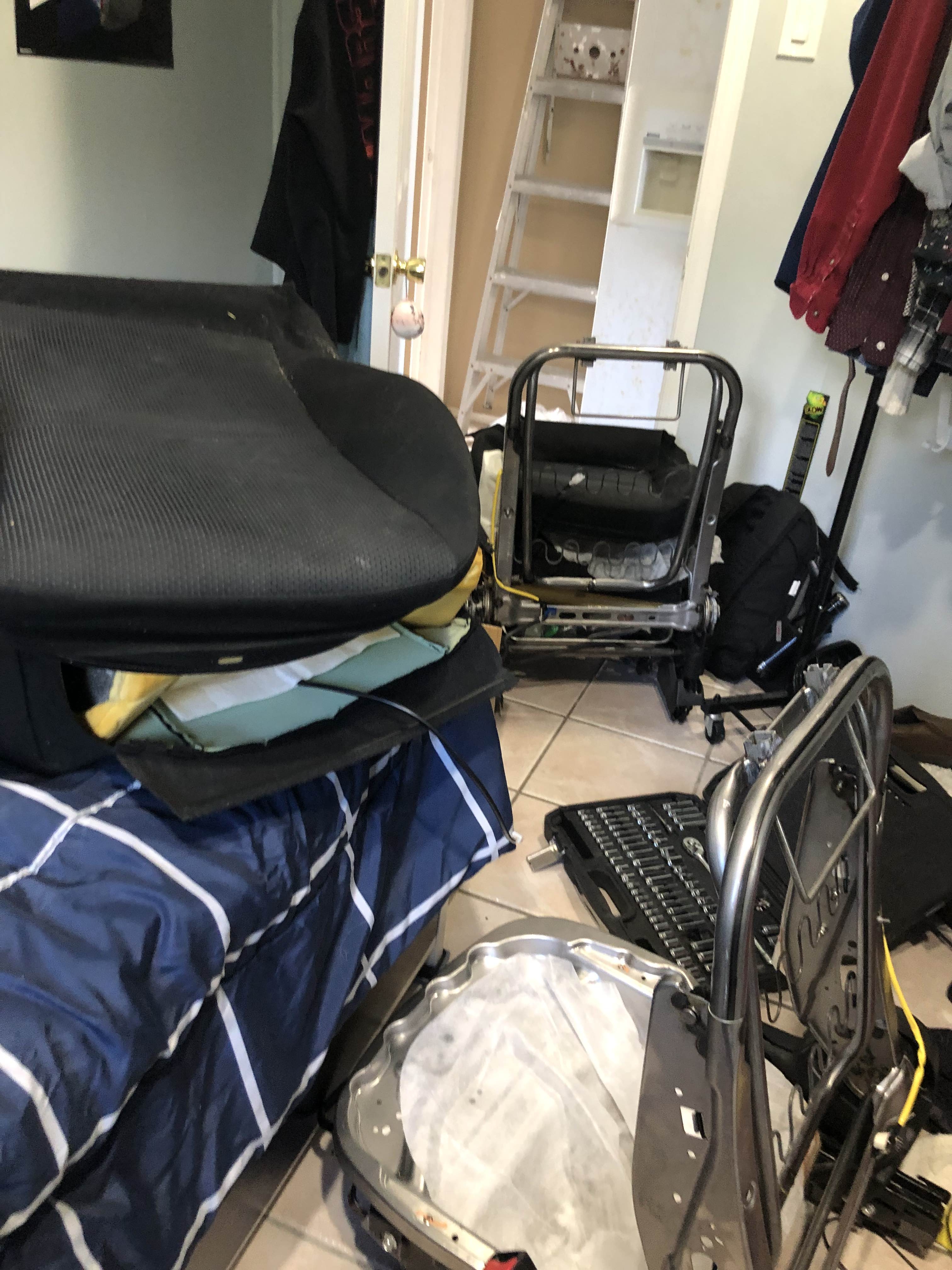
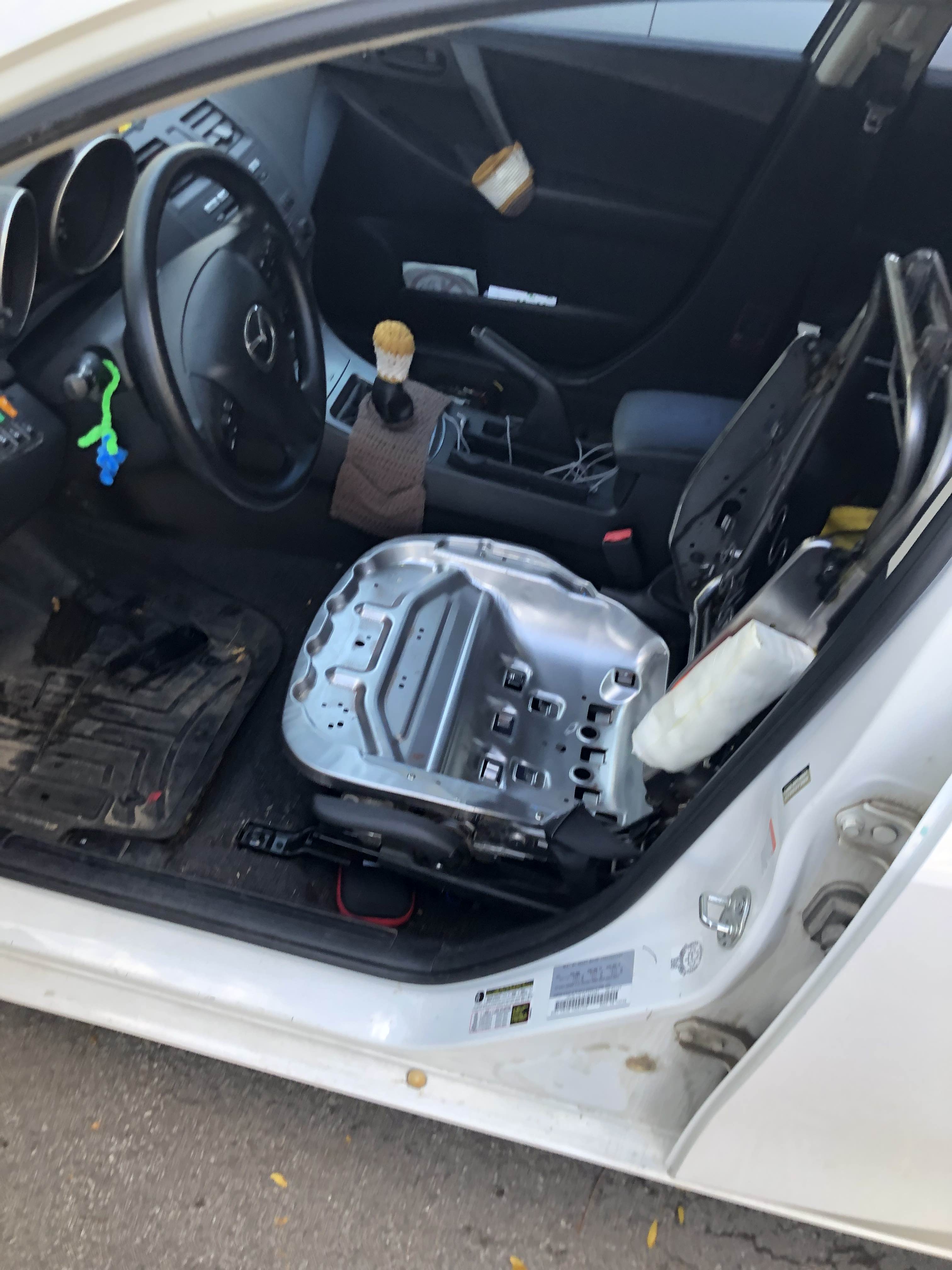
I started by removing the seats and ripping off the upholstery (carefully, following instructions from the shop manual):
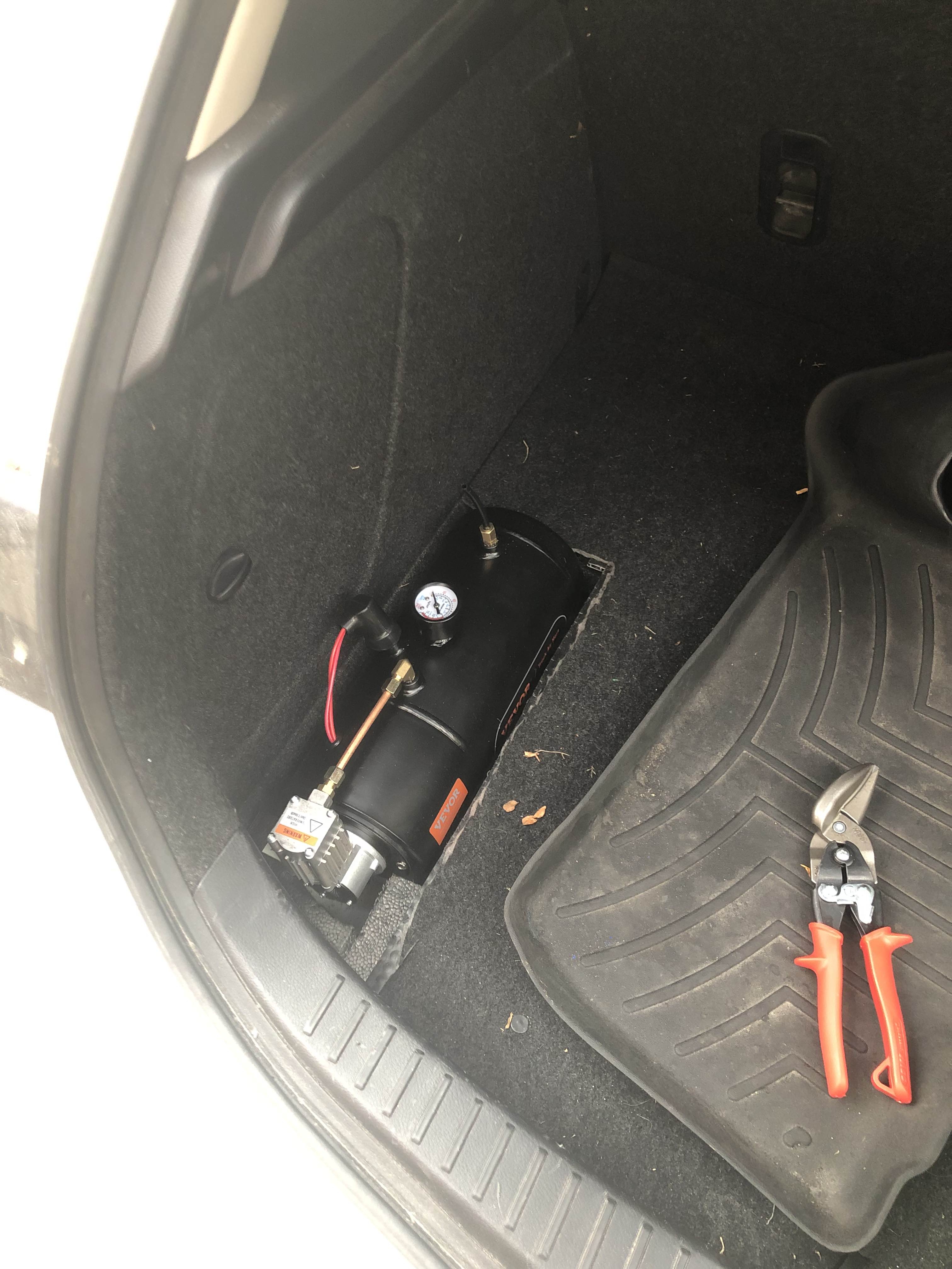
It was a bit weird when I needed to take a trip to the store (for parts for a tank controller - story for another time):
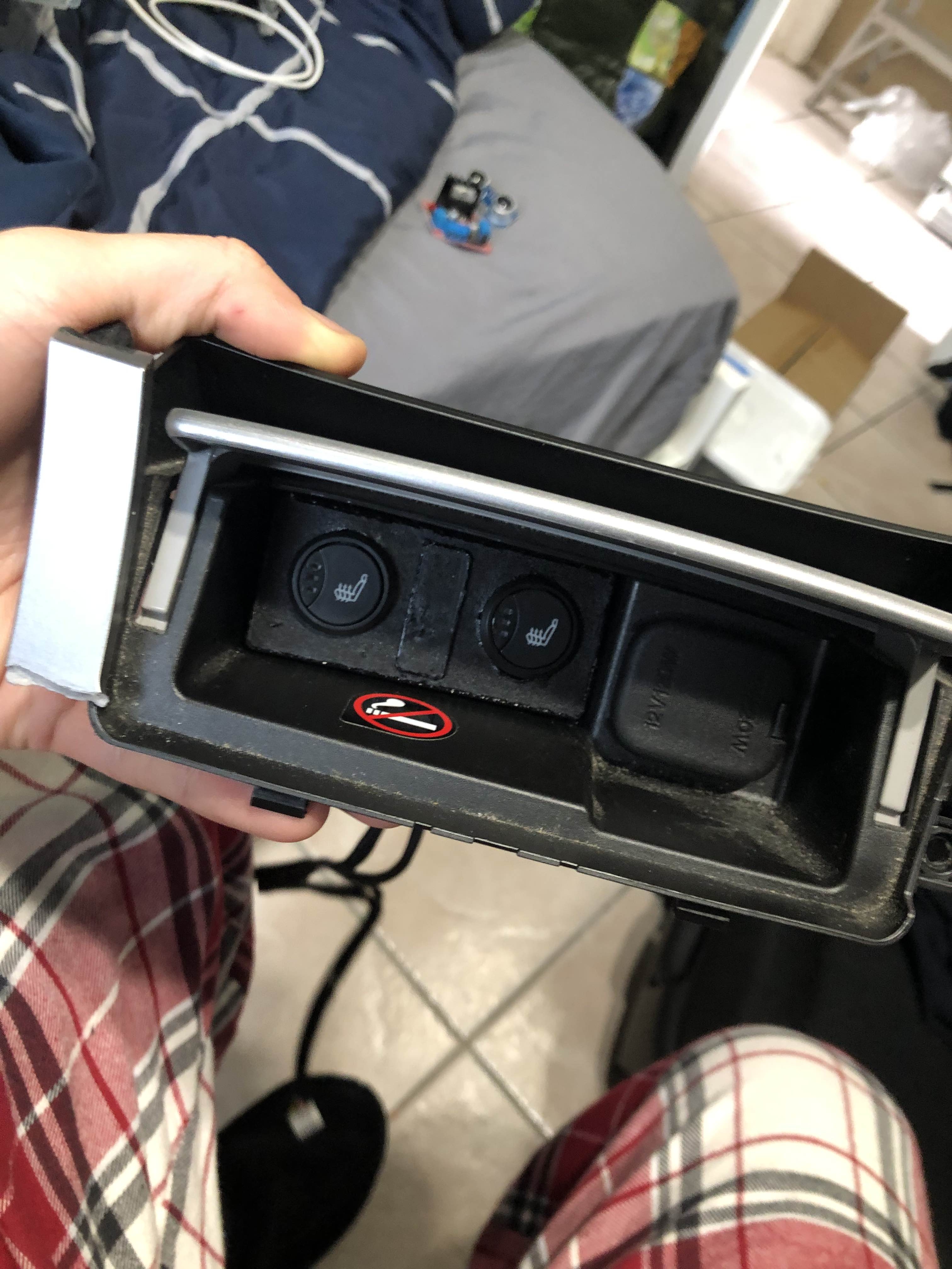
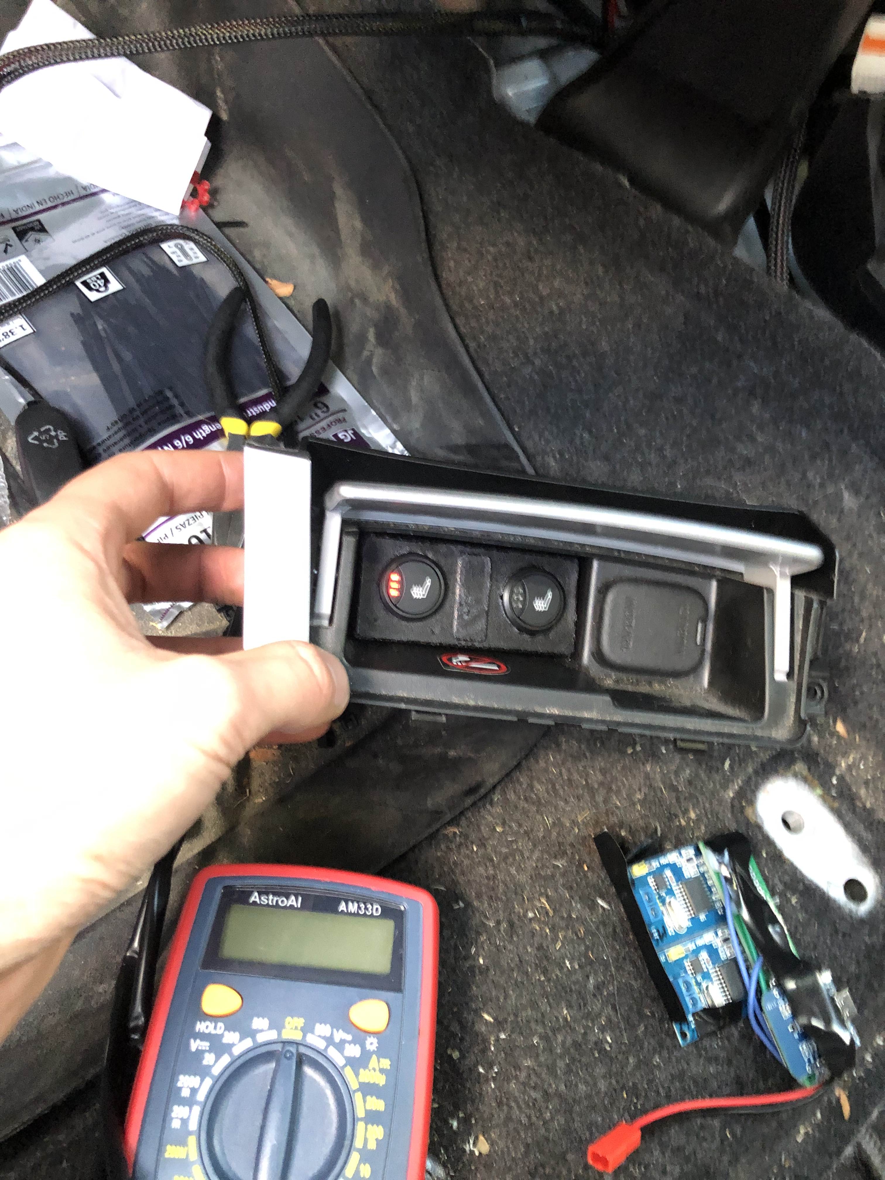
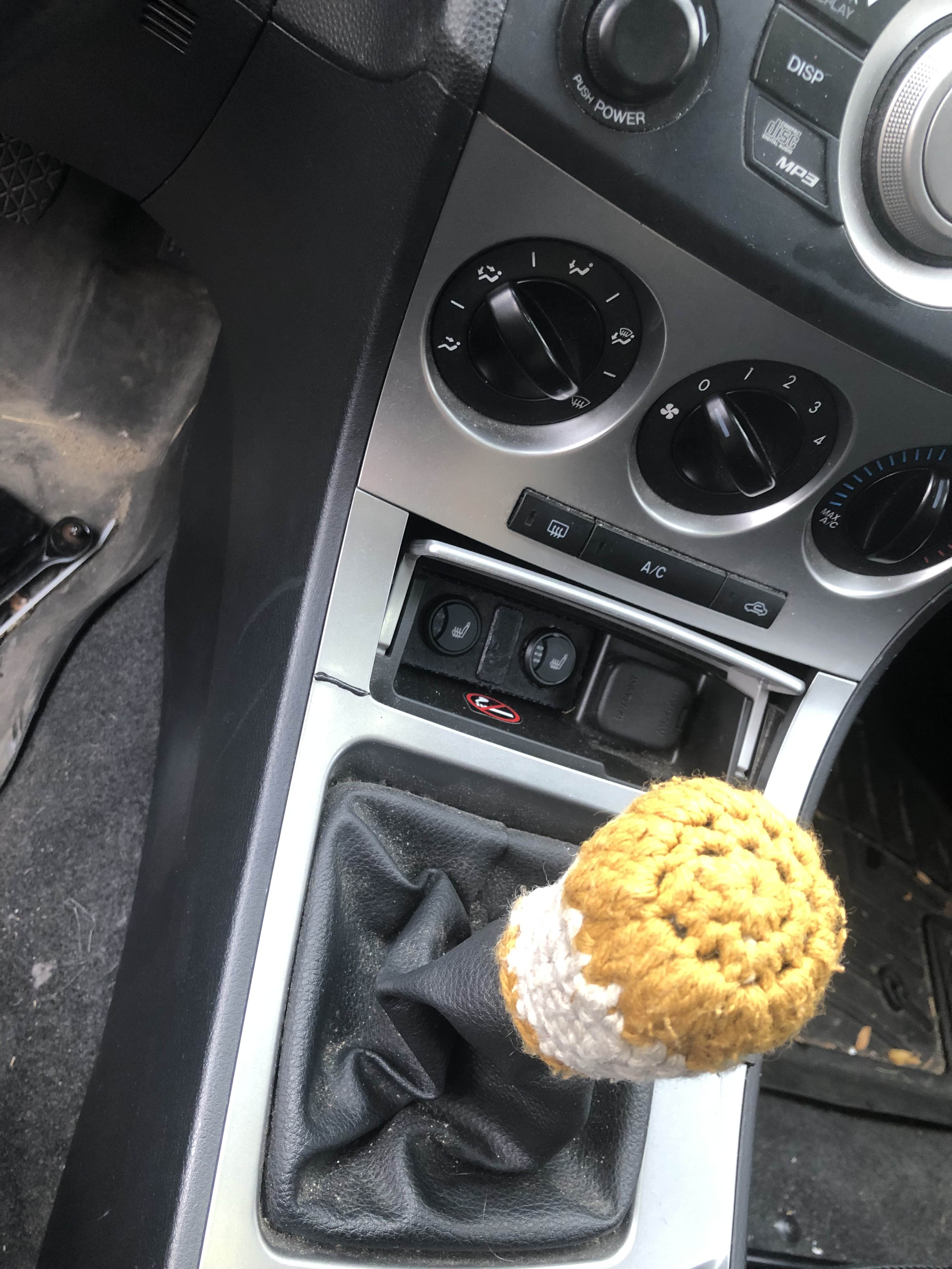
The heated seat kit I got came with 4 heating pads (butt and back), along with the buttons and a control module. When this model of Mazda 3 comes with factory heated seats, they put the buttons next to the cigarette lighter. So I decided to put mine there too.
That's about it for the seats. I had to hook them up to my fusebox (which meant removing all the interior again, joy), and I routed the wire around and stuffed it where it needed to go. I ended up with a pretty neat and tidy install, and the seats work great (a bit too well - even the lowest setting is pretty warm for me!)
Gear Sensor
I had the idea for a while of having a heads up display to show me my speed and gear - inspired by this HUD and this gear sensor.
My setup is a bit different from both. I have my wireless data network to get data to the HUD, and there isn't enough room by my gearshift lever to detect it in the same way - but I came up with something different.
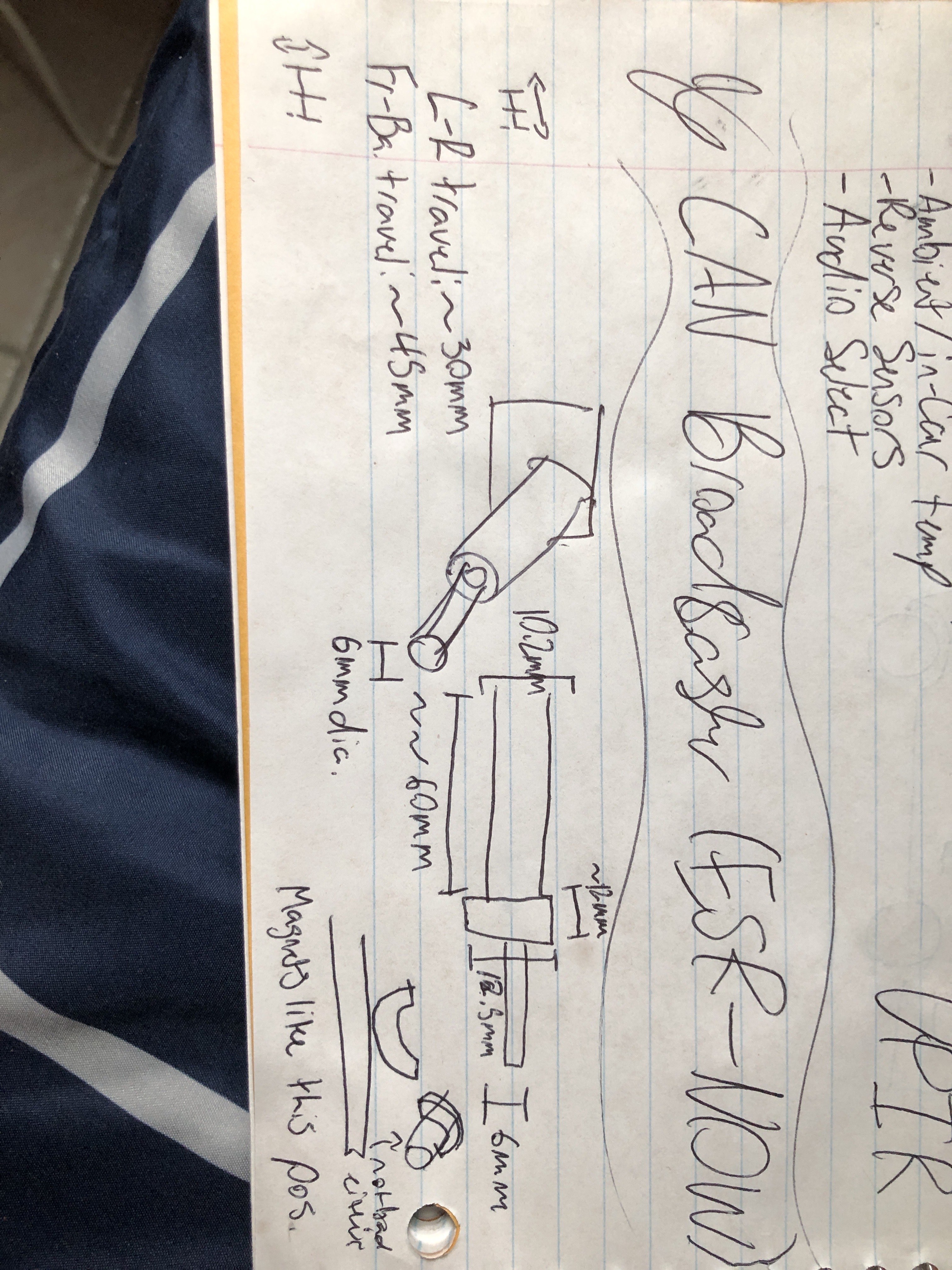
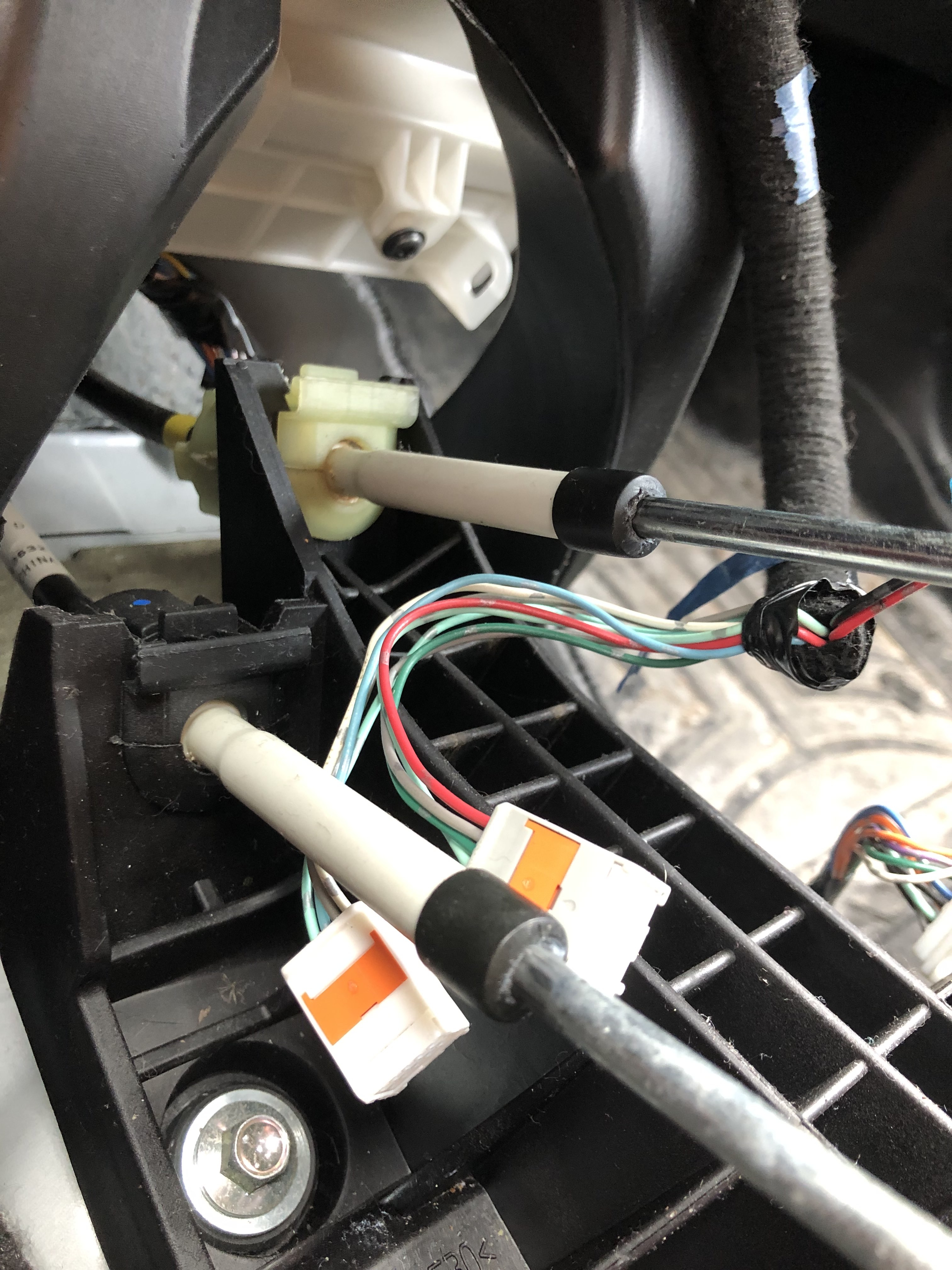
My shifter mechanism has two linkages to the transmission: one for left and right movement, and one for forwards and backwards. The front-to-back one has more travel, but both or just linear slides. I figured I could put a magnet onto the rod and, inspired by the video above, use hall effect sensors to see where they are at. And that's what I did.
It's just 4 hall effect sensors read by an ESP32 and sent wirelessly to the rest of the car. It all took a bunch of iteration - changing thresholds in the code and at least 3 redesigns of the mounts (moving the sensors around). In the end it works pretty good.
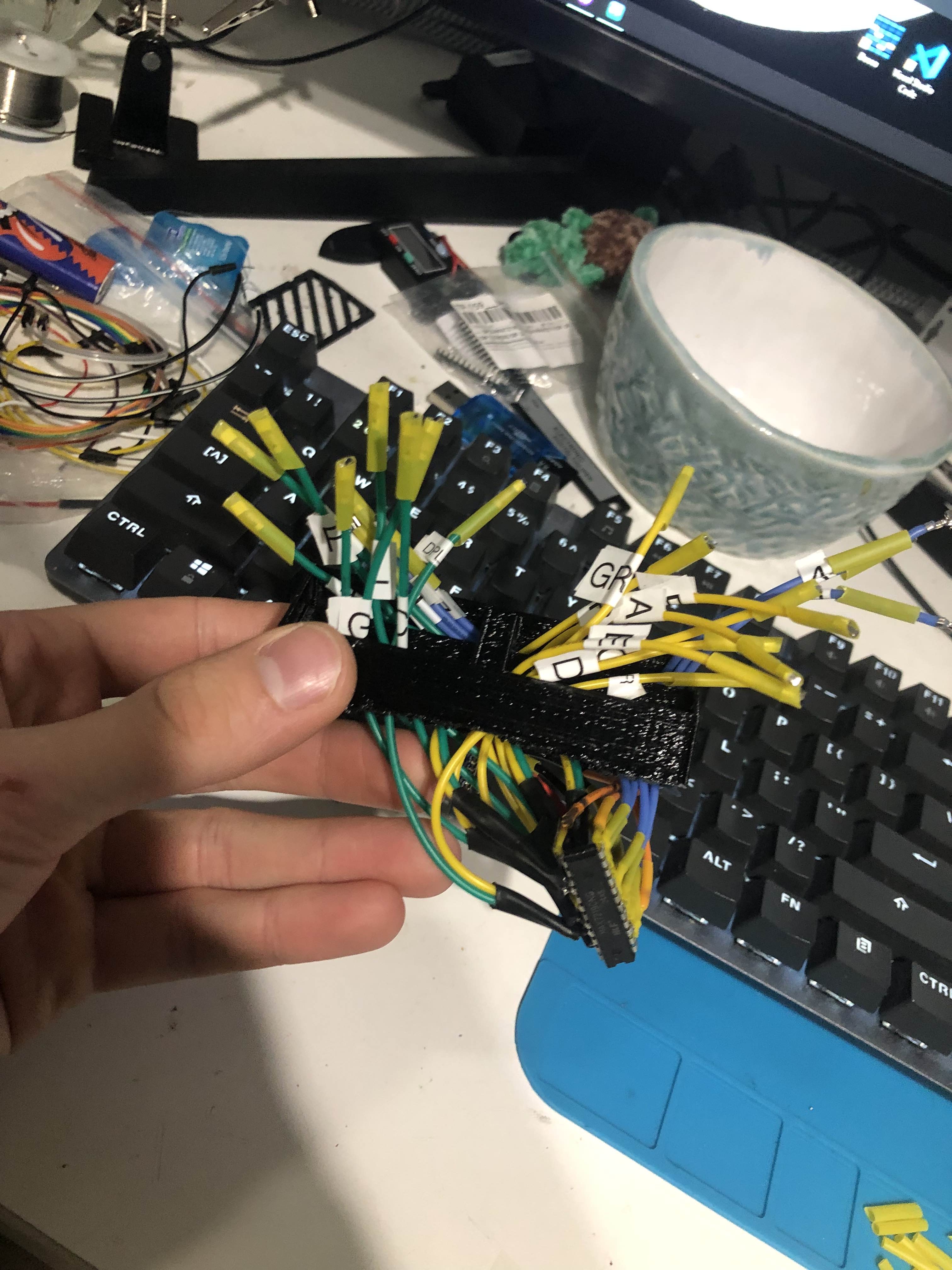
One of the goofier issues I ran into was the fact that the hall effect sensors take and send back 5V logic, but the ESP32's analog pins only accept up to 3.3V. I had interpreted a graph incorrect in the hall effect sensor datasheet, and thought the max voltage would be 3.3V. So I had to splice in this monstrosity:
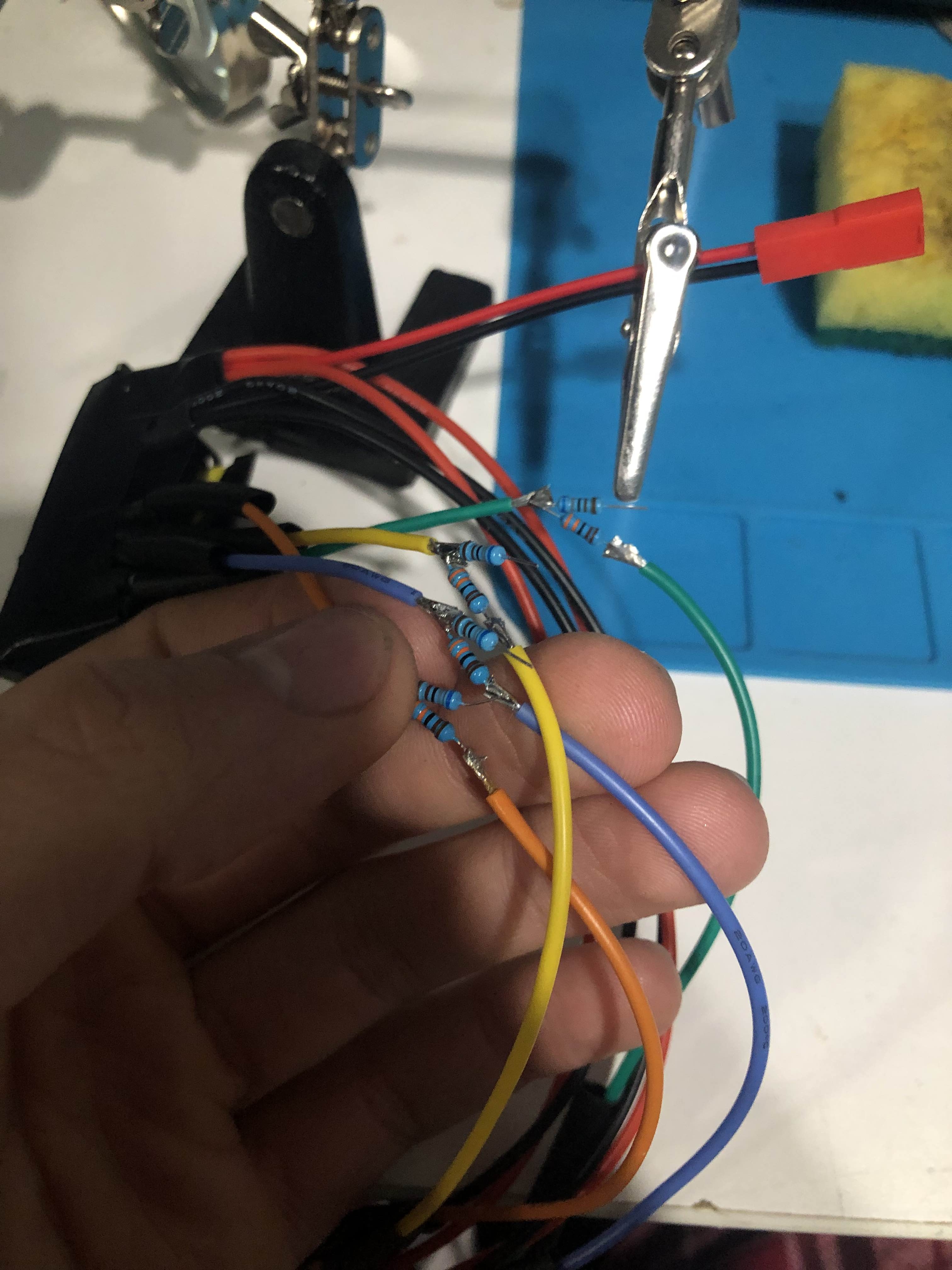
Yeah, I soldered in 8 resistors to drop each line to 3.3V. Yes, it works perfectly.
With that, I could tell what gear I was in. So it was time to start on the HUD!
Heads Up Display (HUD)
I had the gear. I had the speed (from the CAN bus). I just needed to display it.
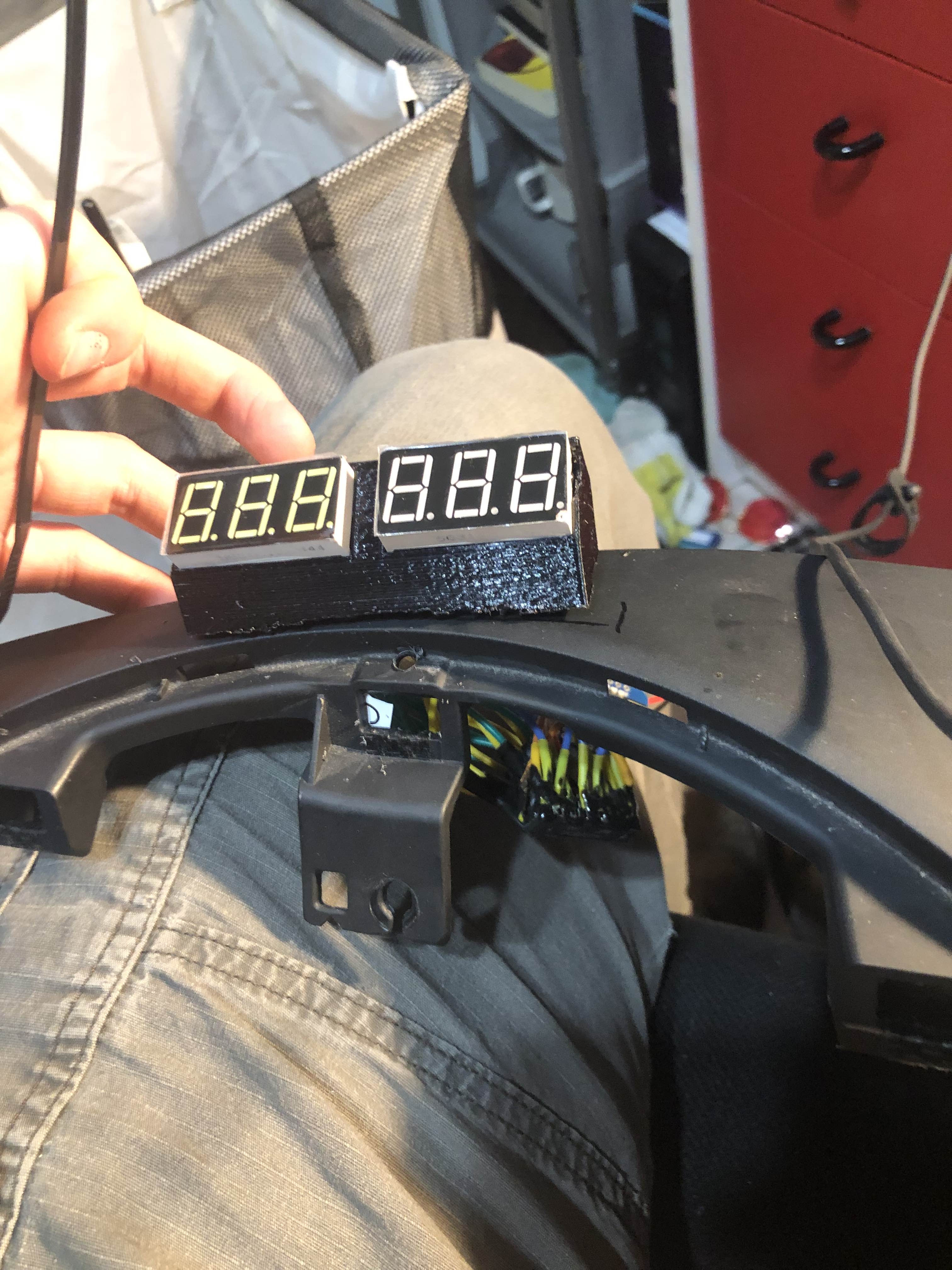
Much like the this HUD, I decided to go with 7 segment displays. Back when I thought of this idea (before any mods even started), I ordered some 7 segment displays for this exact purpose. Luckily, I also got some MAX7219 LED Display Drivers. These came in very handy, letting my control all 6 of my segments and also the brightness of my HUD.
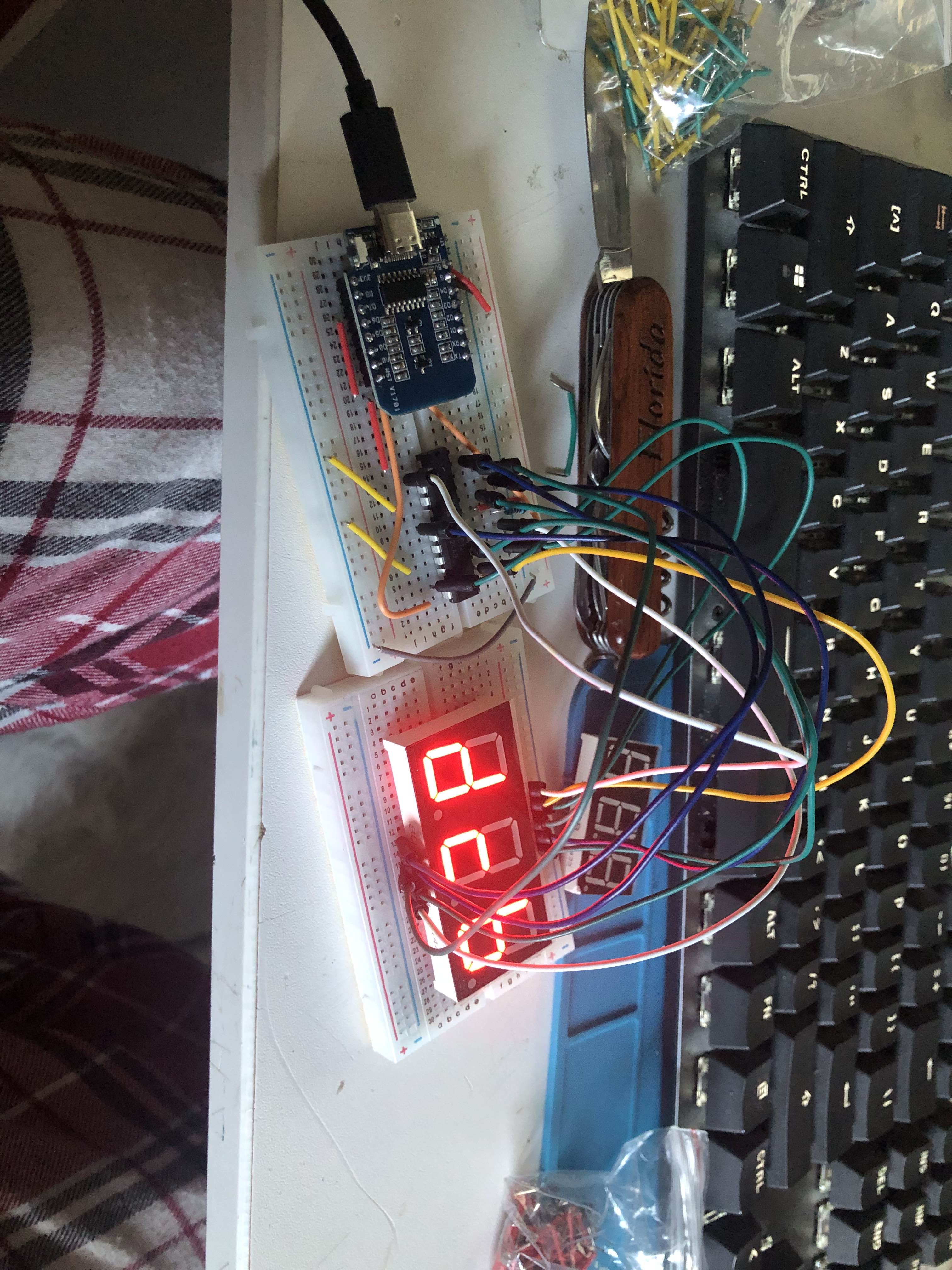
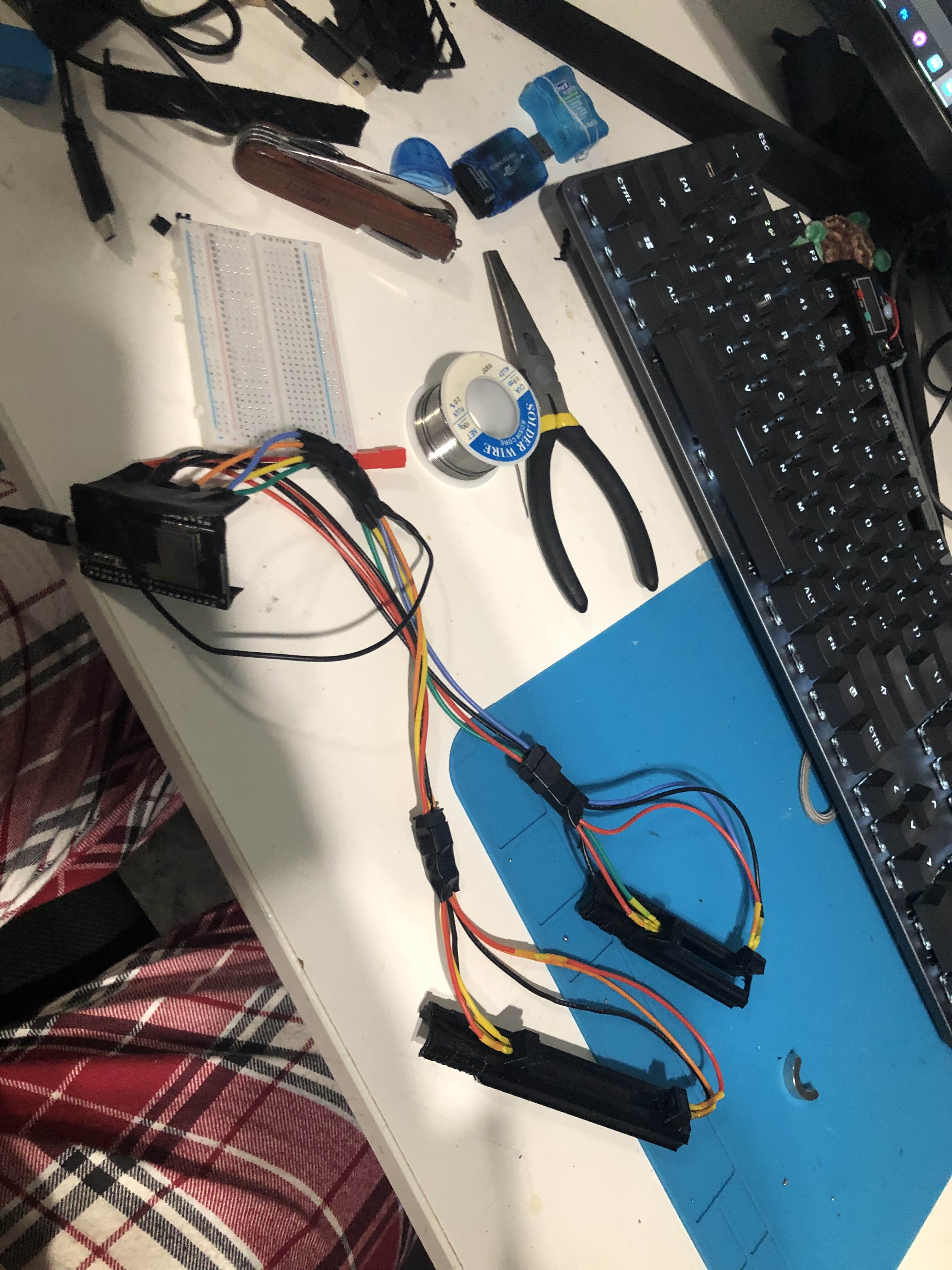
After testing out my leds and MAX7219, I was pondering the best way to assemble the final thing and decided to just directly solder every wire to each pin.
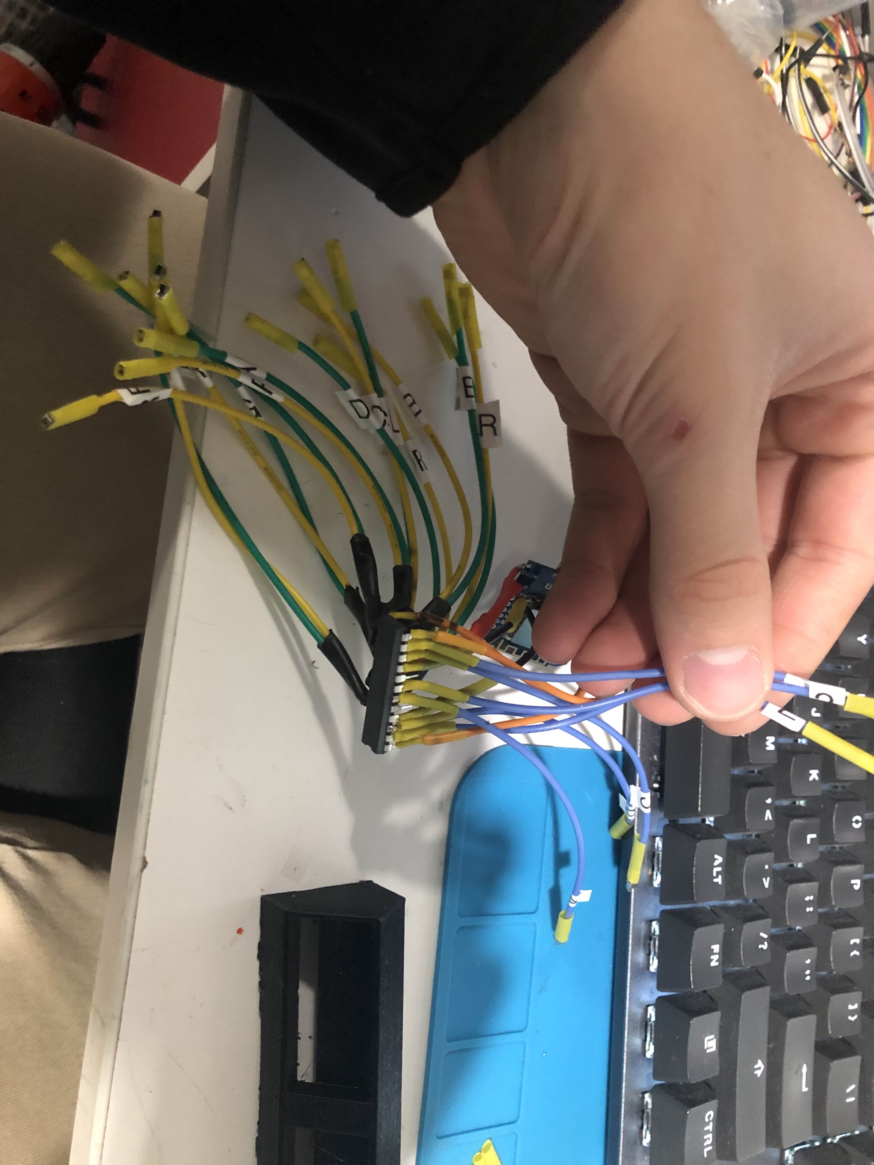
The MAX7219 is only wired to the two 3 digit displays and the ESP8266. No reason to use a protoboard or bread board. I got a $25 label maker which really helped me keep things in order. Some of the labels fell off, but only after I had them attached.
The wires are directly soldered to the MAX7219, but the ends going to the ESP8266 have dupont connector ends crimped onto them. Just made it easy to install instead of soldering. I also obviously heatshrunk/heatshrinked the wires so they wouldn't touch each other and implode.
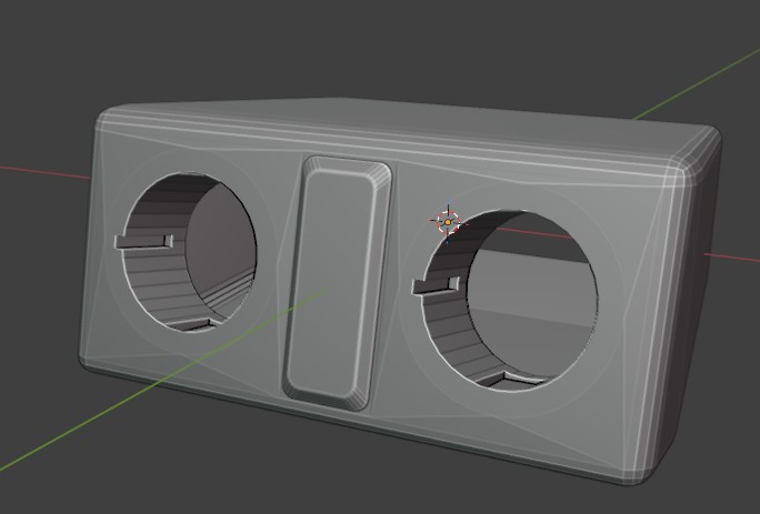
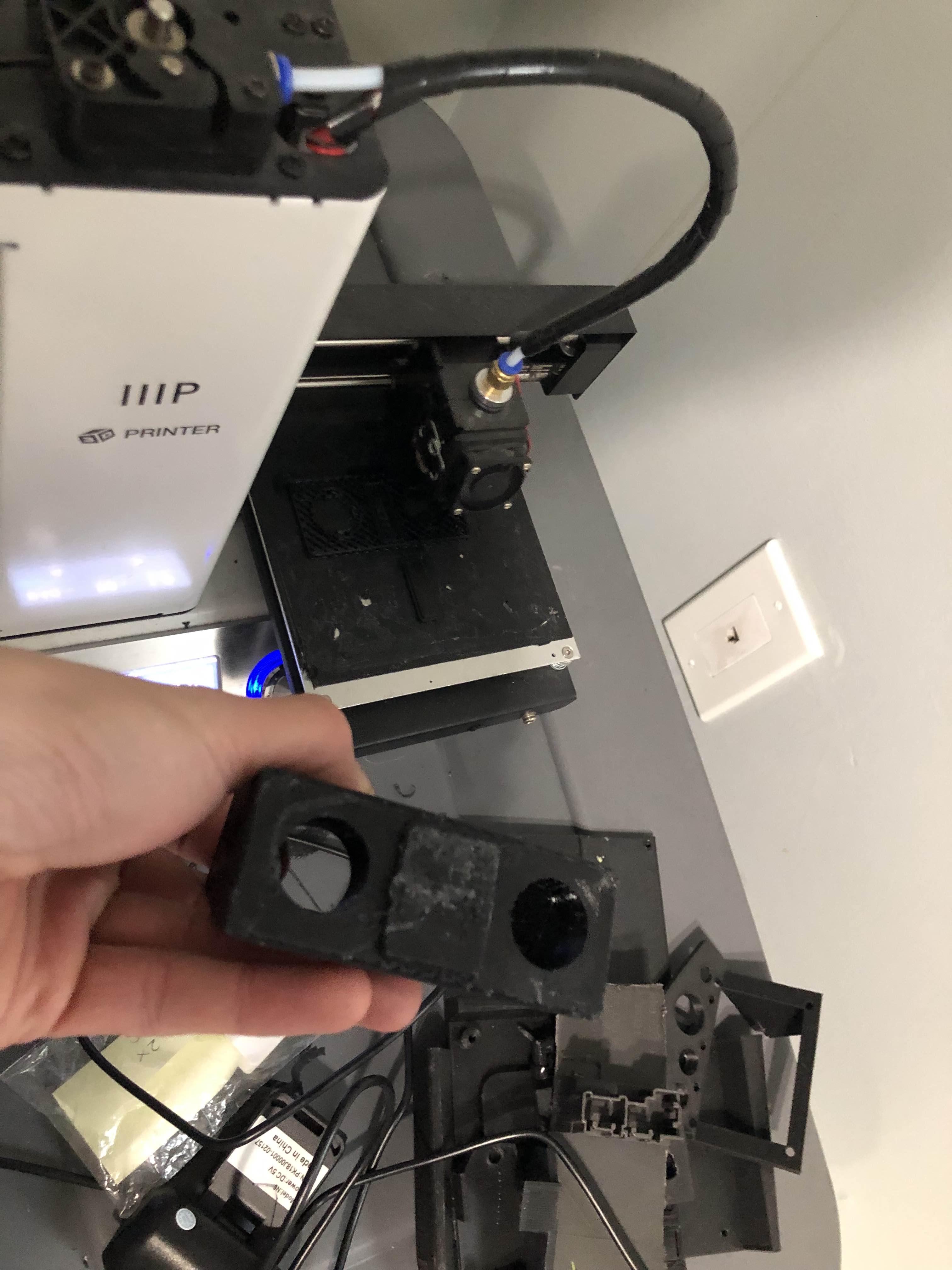
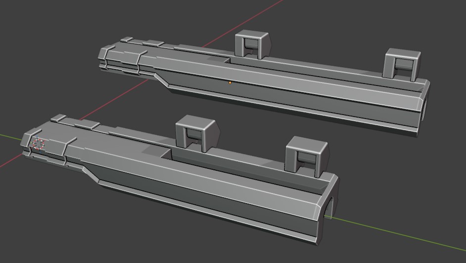
The 3D printed case/enclosure is so simple that I'm not going to cover it :P
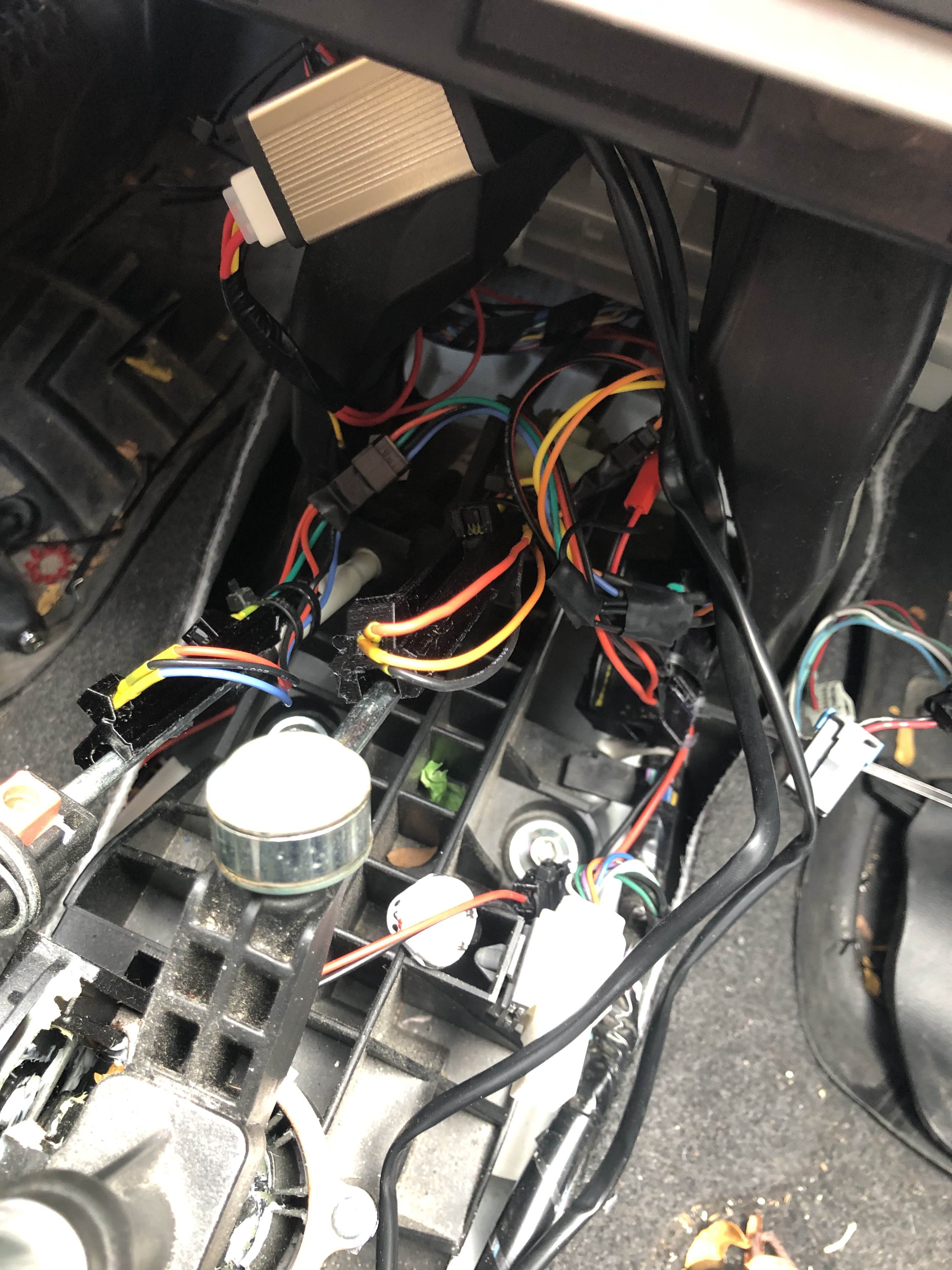
I had to take out the instrument cluster to get at this bit of dash I wanted to install on. Then I just lined it up, drilled a million holes and filed the hole smooth. Pass the wires and modules through and Bob's your uncle.
At this stage I put a bunch of epoxy all the wiring and on the digit displays. I did not want any of these wires making their way lose because getting to the dash is a massive pain.
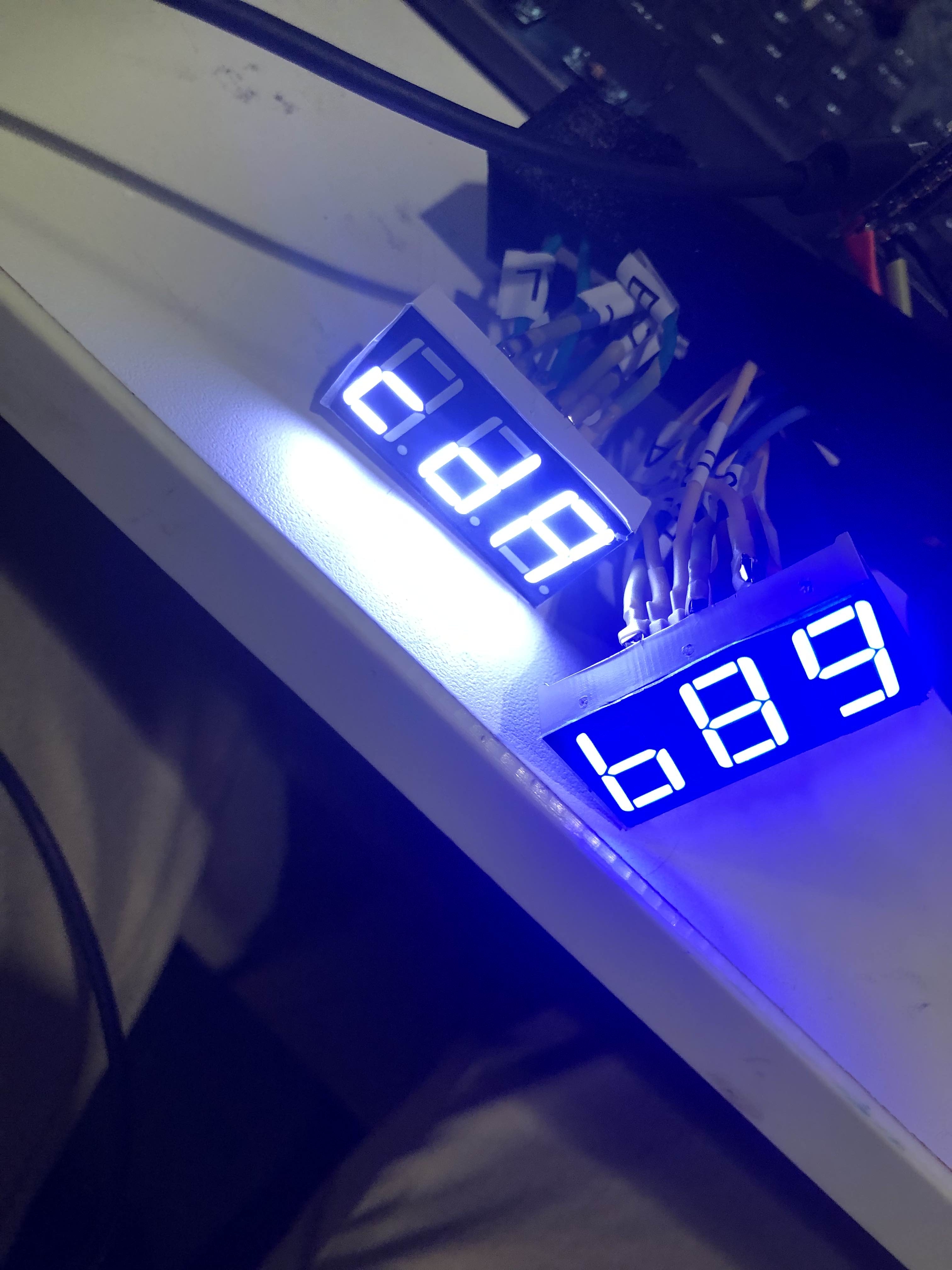
On the code side of things, there is nothing remarkable. The MAX7219 is easy to interface with, and the only thing to keep in mind is you want to write all the characters upside down (since they are reflecting off the windshield). The entire source file is less than 100 lines of code, including the CarComms stuff to receive things wirelessly.
One little quality of life thing: Since this is reflecting off the windshield, I want it to get dimmer at night (I'm not trying to blind myself and it has to be pretty bright in direct sunlight). I considered hooking up a light sensor and calibrating that and blah blah blah, but I figured a better approach would just be to check when the car's lights were on. If that was possible.
I hooked up my laptop to the CAN data center and sniffed some packets. The car did tell you when the lights were on - not lights vs headlights, but either was fine for me. While I was at it I also found what the CAN IDs and values were for the doors being open (the IDs I found online were not correct). I eventually want my little info display (or maybe the HUD?) show what doors are open, and now I have that data.
So now the module dims itself when the car's lights are on. Thanks MAX7219 for making this very easy (I should've used a larger resistor as my lights are a tad bright at night - but not distractingly).
Here's a rough video of it in action.
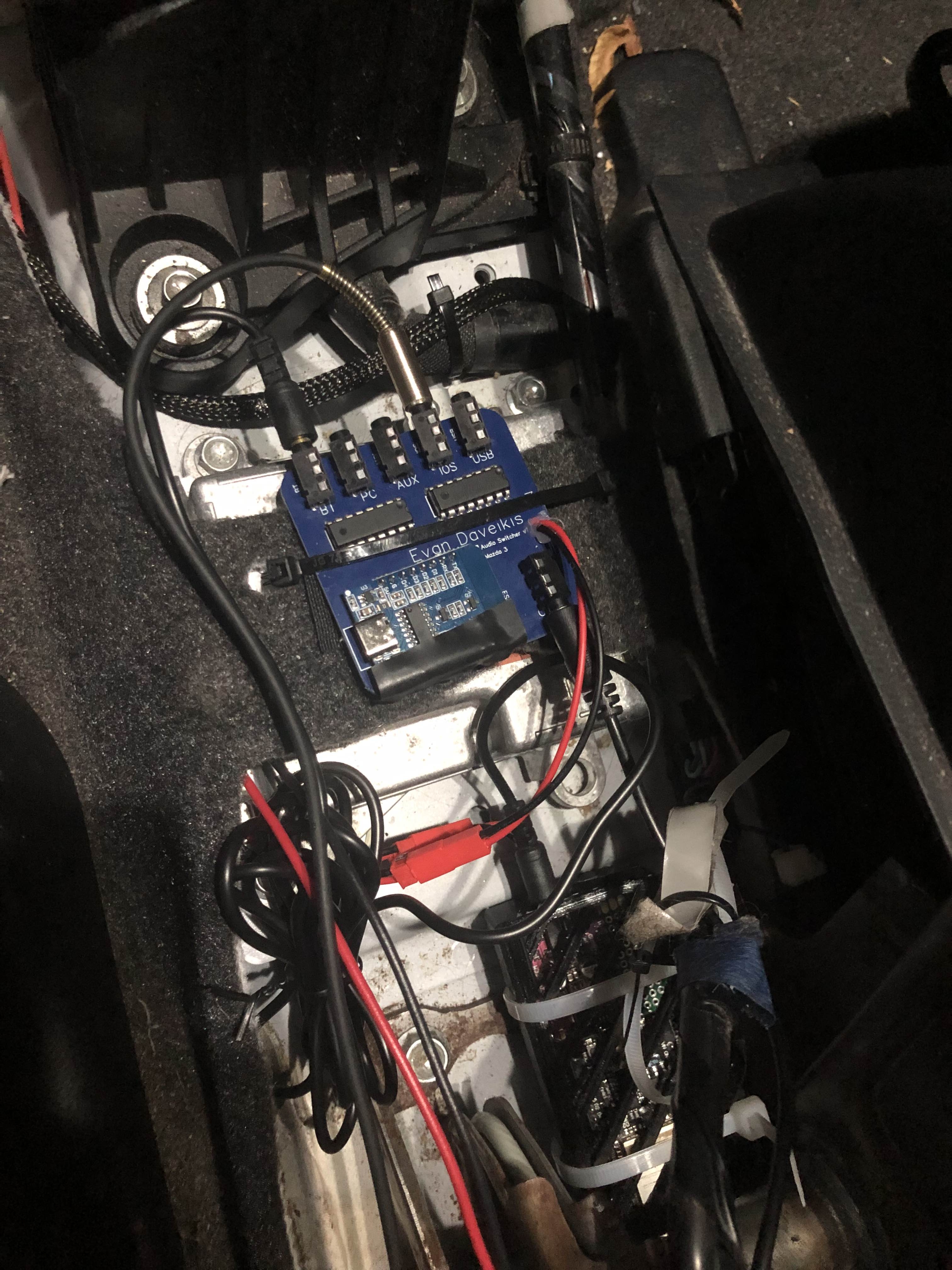
Audio Switcher
The end goal is to have a bunch of audio sources in the car (Bluetooth, the Carputer, AUX, IOS, USB-C). Since I'm just stealing the car's AUX input, I need a way to switch between my 5 sources.
I've mentioned the audio switcher in previous devlogs, but my original plan was to hand solder it all on protoboard. This would've been a huge pain, and I was going to do it just because I didn't know how to design PCBs and it looked scary. But then I tried it anyways.
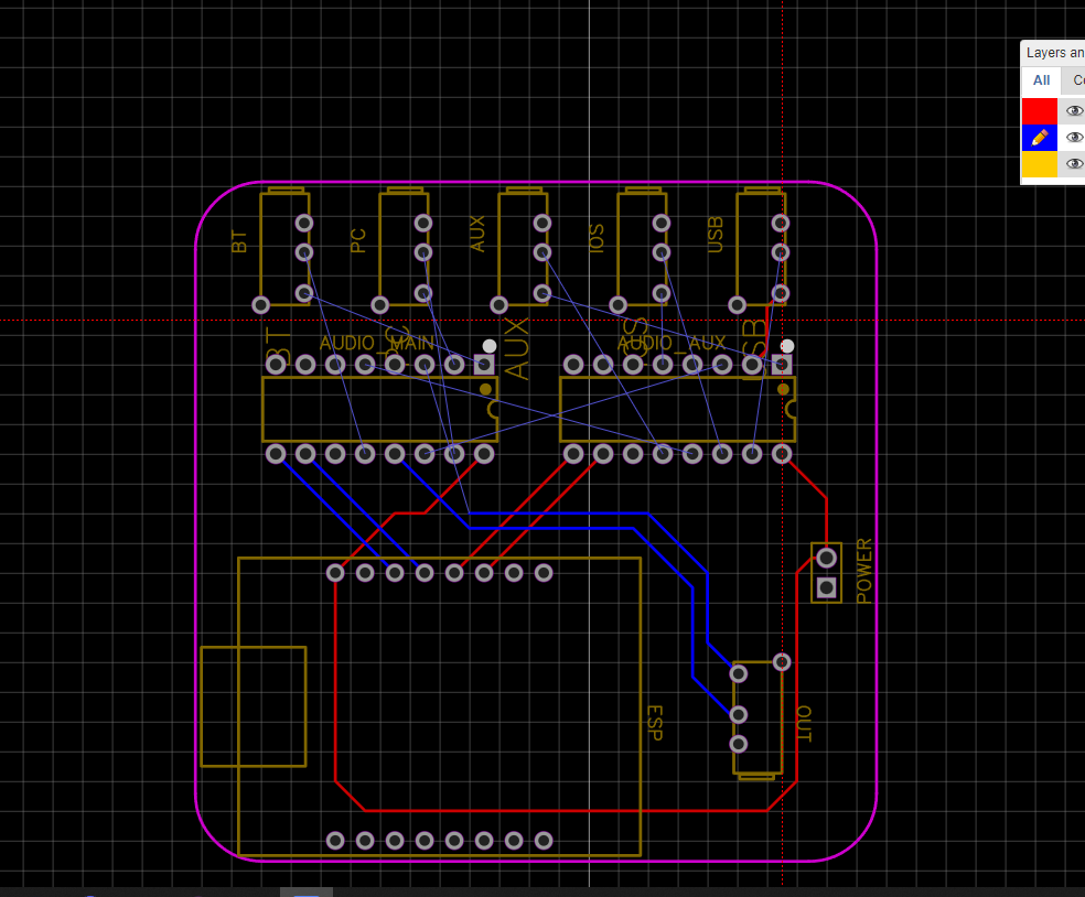
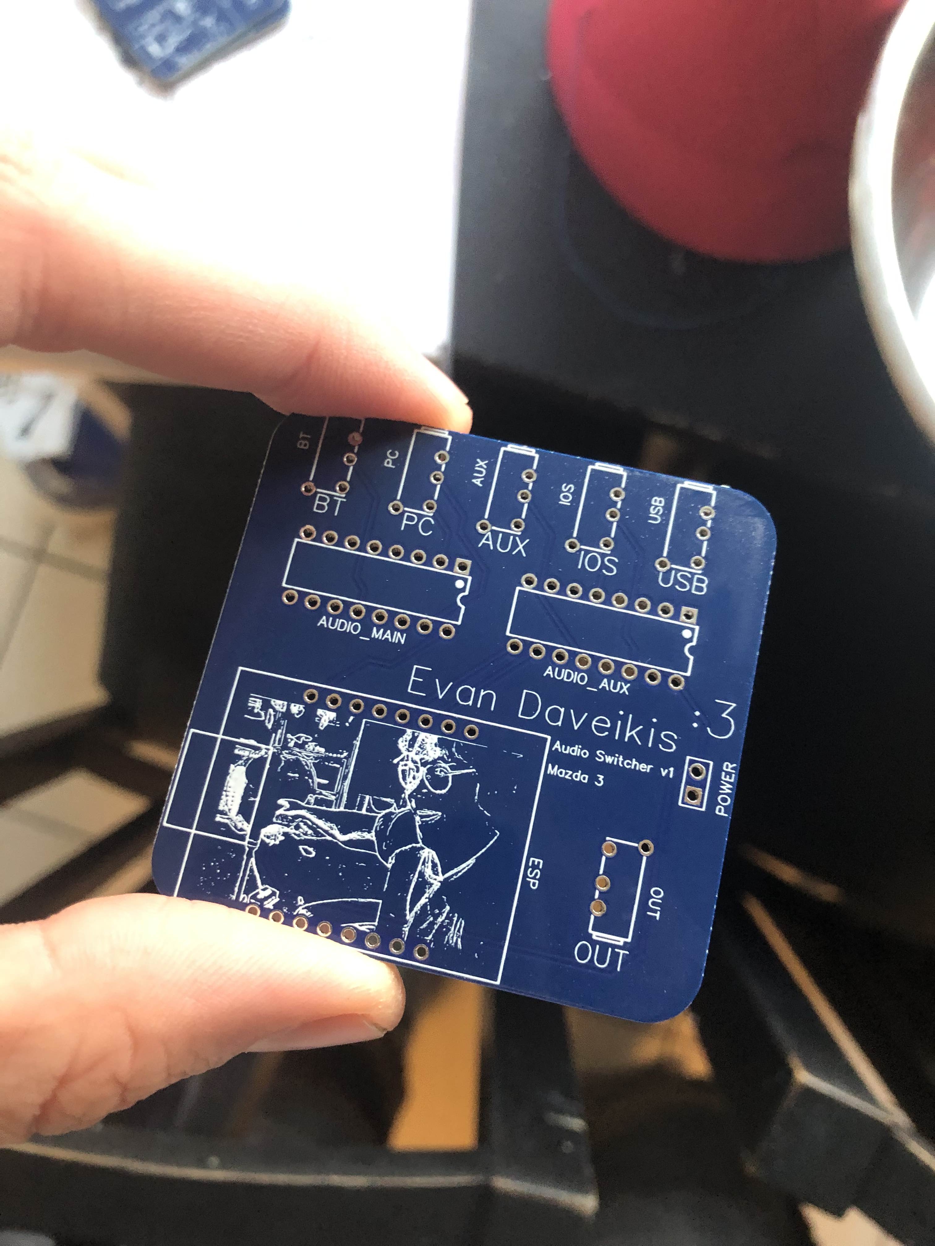
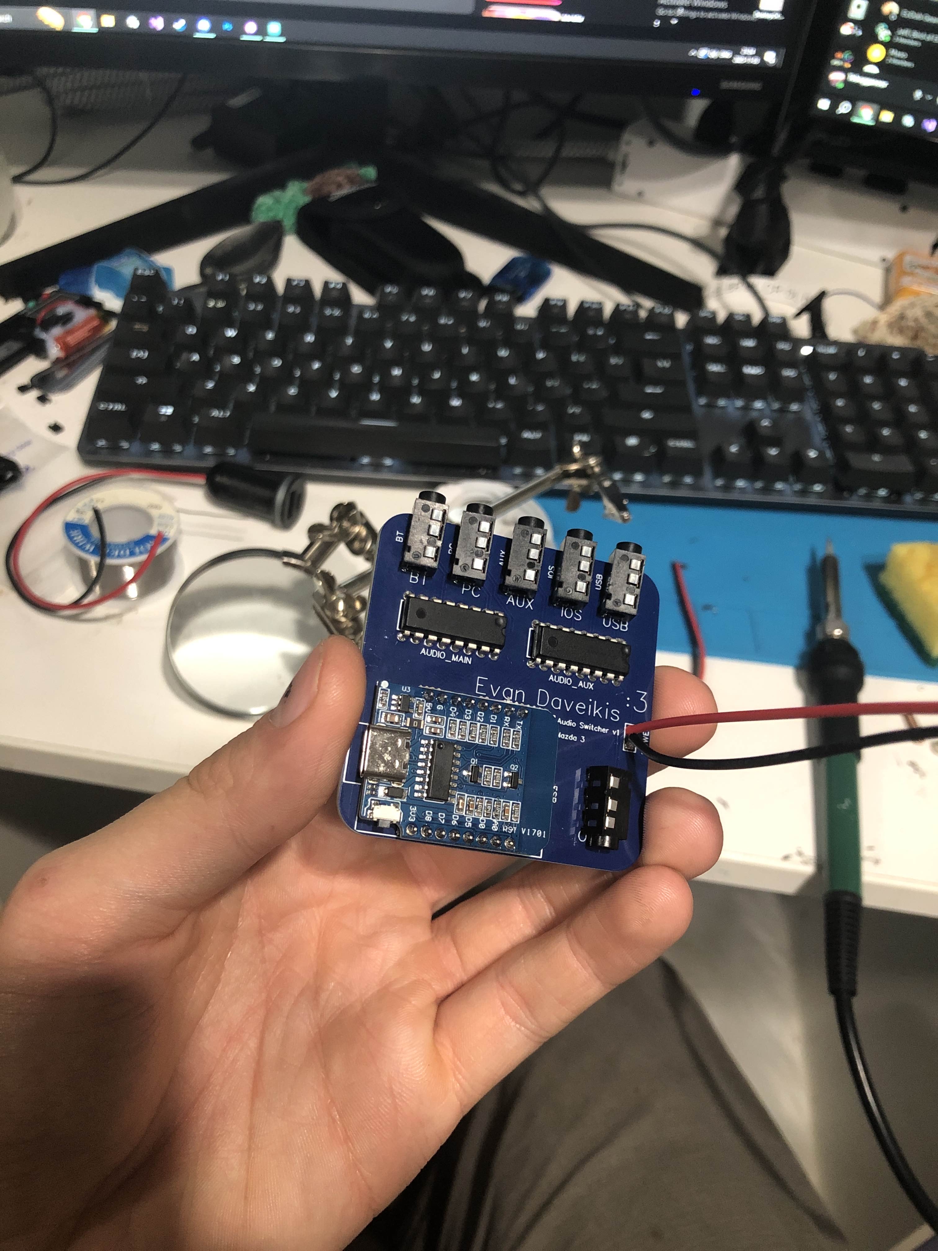
The switcher uses two CD4052B modules to multiplex the 5 audio inputs down to one output, which goes into the hijacked AUX input. The module for displaying the current audio source and switching it has been installed in the car for ages, blindly sending out its signal like a space probe long out of reach.
Teaser